This case study explores the usage of Process Functional Modeling (PFM) as a problem-solving tool in microchip manufacturing. PFM is an innovative way of thinking that involves breaking down a process into its components on multiple levels and generating innovative solutions. The tool enables us to move from general to specific, from process to operations, operations to components, and components to functions. In this article, we provide a real-life example of how a team applied PFM to the microchip manufacturing process. We want to demonstrate its effectiveness in creating a model of failure in the context of the whole process. This information is accessible to all, regardless of prior knowledge of microelectronics.
For general information on PFM, read our related articles Process Functional Modeling with PRIZ Innovation Hub and Functional Modelling with PRIZ Innovation Platform, or watch our Webinar: The Art of Functional Modelling with PRIZ Platform.

The process is related to microelectronics – microchip manufacturing. The purpose of it is to create a SiO2 layer on the surface of a Si wafer.
Equipment
Vertical furnace to heat the wafers in the Q2 atmosphere and perform oxidation on the wafer surface.
Process
The oxidation occurs on the front and the back side of the wafer: Si (wafer) + O2 (gas within the furnace) –> SiO2 (thin film layer on the wafer surface).
The process is performed in batches of up to 150 wafers in every run.
Requirements
Create a SiO2 thin layer with a certain thickness and low sigma – low standard deviation of the thickness between the wafers and within the wafer
Failure
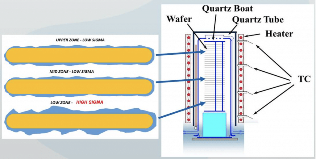
Wafers from the lower zone have higher thickness and significantly higher within wafer sigma (standard deviation of the thickness within the wafer)
As the platform suggests, we built the problem statement using the three steps as shown below.
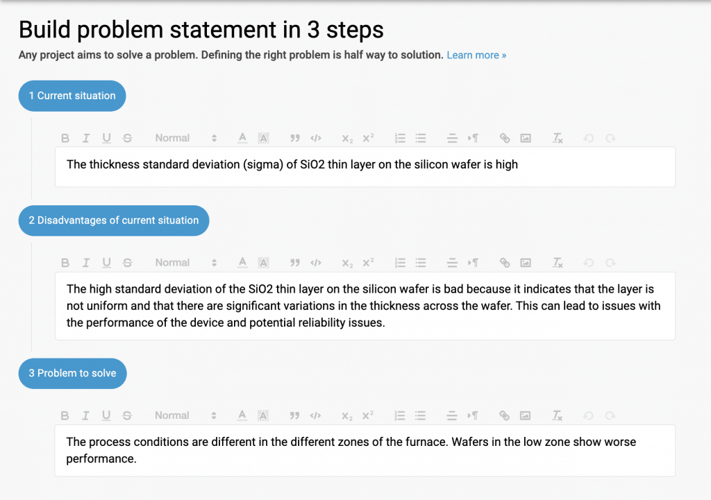
The final problem statement is as follows:
The process conditions are different in the different zones of the furnace. Wafers in the low zone present worse performance.
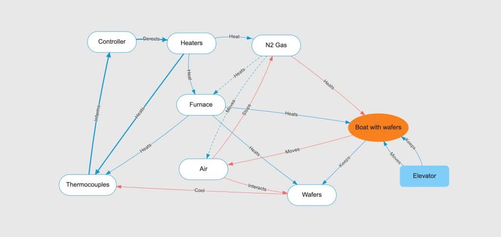
Before delving deeper into the subject, let’s review the specifics of this oxidation process itself. The process is performed inside a vertical furnace, where the furnace temperature is maintained by three different heaters in three zones. The temperature in these zones is measured using various thermocouples.
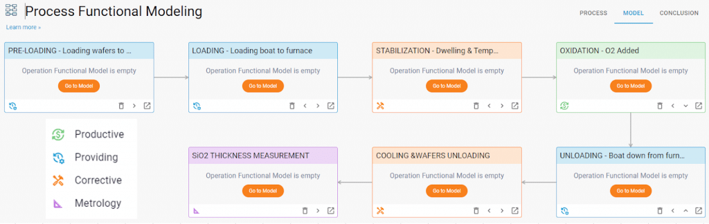
The process consists of several distinct steps:
The entire process can be broken down into the following operations:
After defining the operation types, our process now looks like the following:
Following the process of PFM, the next phase in the analysis involves constructing a Functional Model for each operation in the process. This is particularly important to build PFM for every operation when there isn’t a clear culprit for the problem at hand.
An example of the second operation (LOADING) is shown below.
After building the functional model for each operation in the process, the platform calculates its respective functional and problematic levels. The effectiveness of each operation is determined by the ratio of its functional rank to its problematic rank.
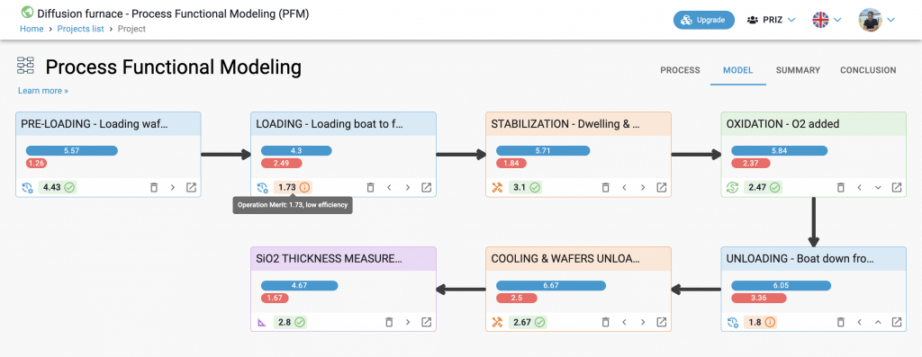
It is evident that the LOADING and UNLOADING operations appear problematic. Additionally, the LOADING operation has the lowest effectiveness ratio. This result is significant as it defines the direction of our thinking:
The problem arises during the movement of wafers within the furnace.
Using the concept of wafer movement, let us explore potential models for failures of the bottom zone wafers’ thickness sigma (i.e., the standard deviation of the thickness).
As the wafers are loaded into the furnace at 300C, the cold wafers cool down the bottom thermocouple (TC). This causes more power to be added to the bottom heaters, leading to strong overheating of the bottom zone.
While loading the wafers, the flow of N2 primarily removes the air from the furnace, but some amount may remain, which could collect in the bottom zone of the furnace. As a result, the wafers in the bottom zone will start oxidizing earlier and receive more O2, leading to an uneven SiO2 thickness distribution.
During the unloading process, the wafers at the bottom of the boat are exposed to the atmosphere first, which results in them having a higher temperature compared to the rest. Additionally, due to their proximity to the massive bottom flange, they retain their temperature for a longer period.
There are most likely more than just these two possible options to solve the problem. We will leave that to you to think about and propose in the comments. These are the two things we ended up implementing in the process.
That is it. You can find the fully detailed project published under PRIZ Hub at SiO2 thin film creation in Diffusion furnace.